
The Cable Is the Measurement: Rethinking Phase Stability in RF Test
Originally published in everything RF
By Phil Lenk, Product Manager at Micro-Coax
 Every RF measurement is only as good as the signal path that delivers it. A vector network analyzer calibrated to sub-tenth-of-a-degree phase accuracy is functionally compromised if the test cable between the instrument and the device under test is introducing its own phase drift with every flex. For test engineers working at the bench, on the production floor, or out on the flight line, that cable is not a passive conduit; it is an active variable in the measurement equation. It always has been. The difference today is that the frequencies are higher, the margins are tighter, and the cost of uncontrolled cable-induced variation has never been greater.
RF and microwave testing is being pushed into frequency ranges and operational environments that expose the limitations of conventional test cable design. The problems are not new, but the stakes are higher. Understanding what those problems are, why they are getting harder to ignore, and what a well-engineered cable assembly can do about them is essential for any engineer selecting test hardware for demanding high-frequency work.
Phase Stability: A Fundamental Constraint
Phase stability is one of the central electrical requirements of any RF test cable, and it is the property most vulnerable to the realities of how test cables are actually used. Phase is a function of a cable’s electrical length, determined by its physical length, dielectric constant, and propagation velocity. In a perfectly static, temperature-controlled environment, the phase of the cable does not change. In the real world of active test environments, it may change significantly, especially if you’re not using the right test cable.
Mechanical perturbation such as bending, twisting, pulling, and repositioning, alters the physical geometry of the cable and with it the electrical length. Temperature variation changes the dielectric properties and the dimensional stability of the materials. The result is phase change: a shift in the electrical length of the signal path that the test instrument has no way to distinguish from a property of the device under test. At lower frequencies, these effects are often small enough to dismiss or manage through periodic recalibration. As frequencies increase, the relationship between physical geometry and electrical performance becomes increasingly sensitive, and the same mechanical event that caused a negligible phase shift at 6 GHz can corrupt a measurement at 40 GHz.
At 70 GHz, where a single millimeter represents a meaningful fraction of a wavelength, the demands on cable construction are severe. The margin for phase variation that can be absorbed without affecting measurement integrity is vanishingly small. Any design that relies on external mechanical protection alone, while leaving the internal cable geometry free to shift under movement, is working against the physics of the measurement environment it is supposed to serve.
Where Conventional Test Cables Fall Short
The dominant approach to test cable durability has historically been external armoring: a metallic braid or coiled outer layer that provides mechanical protection against crushing, kinking, and abrasion. This approach addresses some of the failure modes associated with test cable handling, but it does not address the core electrical stability problem, and it introduces its own set of practical liabilities
Armored test cables are stiff by design. That stiffness is the mechanism by which they resist deformation, but it also makes them difficult to route through the dense cable management of modern automated test racks, impractical to maneuver in the tight quarters of flight-line maintenance, and prone to applying persistent bending force on connector interfaces, accelerating wear on both the cable termination and the test equipment port. In high-volume production environments where connectors are cycled hundreds of times daily, this mechanical stress is a meaningful contributor to equipment maintenance costs and downtime.
Standard flexible cables avoid the routing and handling problems of armored assemblies but sacrifice the stability and durability that demanding measurements require. Every repositioning event introduces a phase variation that may or may not fall within the tolerance of the current calibration state. In R&D, this shows up as scatter in characterization data and eroded confidence in results. In production, the consequences are more direct: recalibration takes time, and undetected drift means devices are being accepted or rejected based on errors introduced by the cable, not by the device under test.
“As RF and microwave testing pushes to higher frequencies and faster digital speeds, maintaining measurement accuracy becomes increasingly difficult,” explains Jerico Sabas, Product Manager at Micro-Coax. “Many test environments where cables are frequently moved or reconfigured like production racks, flight lines, and field test setups now operate outside of tightly controlled laboratories. The test cable is often the least scrutinized component in the signal path, but it can be the most consequential source of measurement uncertainty.”
Why the Problem Is Getting Harder to Ignore
The RF test landscape is being reshaped by a convergence of industry trends: higher frequencies, more demanding environments, faster throughput, and less tolerance for variation.
The deployment of 5G networks and the early-stage development of 6G require signal characterization at frequencies and bandwidths that were specialized research applications just a few years ago. Advanced radar and electronic warfare systems in aerospace and defense push test requirements progressively higher into the millimeter-wave range, with characterization needs extending to 70 GHz and beyond. Semiconductor test for high-speed data converters and RF transceivers increasingly involves signal integrity measurement at frequencies where the cable’s own electrical performance is a first-order concern, not an afterthought.
The automotive sector has emerged as one of the more demanding and highest-volume new test environments. ADAS systems, autonomous driving platforms, and collision avoidance radars operate at 77 GHz and above, creating a high-volume production test requirement at frequencies that demand the same rigor as defense and research applications, but at automotive production scale. The density of test points, the rate of connector cycles, and the expectation of continuous uptime in these environments place requirements on test cable assemblies that standard flexible or armored cables were not designed to meet.
Across all these segments, the pressure is consistent: the test cable is the interface between the instrument and the device, and its performance directly constrains the quality and reliability of every measurement made through it. A cable that introduces phase variation requires recalibration. Recalibration takes time, slows throughput, and introduces its own risk of operator error. In a production environment, this compounds across thousands of test cycles.
What an Improved Test Cable Design Looks Like
Addressing the limitations of both armored and standard flexible test cables requires a different structural approach, one that builds mechanical stability into the cable’s interior rather than relying on external protection adding bulk and rigidity without solving the phase stability problem. The key design elements that separate a high-stability test cable from a conventional one include the internal ruggedization architecture, the choice of outer conductor construction, the dielectric material and density, and the approach to shielding.
Internal ruggedization incorporates high-strength fiber materials within the cable structure itself and provides resistance to the tensile and torsional forces that cause phase variation under movement without adding the stiffness of external armor. An outer conductor wound helically rather than braided maintains more consistent electrical geometry through bending and flexure, reducing the impedance variation that a conventionally braided conductor introduces at higher frequencies. An ultra-low-density PTFE dielectric provides a stable and consistent velocity factor that does not shift meaningfully with temperature or handling. Together, these design choices minimize the relationship between mechanical events and electrical change, which is precisely the problem that phase stability requirements demand solving.
Durability also cannot be treated as separate from electrical performance. A cable that degrades mechanically over its service life will degrade electrically as well. In a test environment, that degradation may be gradual enough to escape notice. Flex cycle ratings—the number of bending cycles a cable can sustain before its electrical performance degrades outside specification—are a meaningful indicator of whether a cable is designed for the actual duty cycle of a production or R&D test environment, or for something far less demanding.
AccuPhase® Assemblies: A Purpose-Built Response
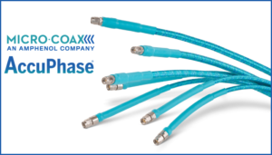
Micro-Coaxdeveloped the AccuPhase® RF test cable assembly family specifically to address these requirements, delivering high phase and amplitude stability in a flexible, internally ruggedized design that is practical for laboratory, production, and flight-line use. The AccuPhase® line draws on Micro-Coax’s UTiFLEX® cable assembly heritage. It incorporates ARACON® braid, an aramid fiber material that provides exceptional tensile strength, dimensional stability, and electrical stability as an internal structural element. It also maintains flexibility without adding the bulk or handling resistance of external armor. Combined with a helically wrapped outer conductor and ultra-low-density PTFE dielectric, the construction minimizes amplitude and phase change caused by movement, temperature fluctuation, twisting, and pulling across frequencies from DC to 70 GHz.
“By focusing on internal ruggedization, phase stability, and real-world usability, we created a test assembly that engineers can trust to deliver consistent results day after day, whether they’re on the bench, in production, or on the flight line,” says Jerico Sabas. “The goal was to remove cable-induced measurement variation as a source of uncertainty in the test setup, to make the cable a known quantity rather than a variable.”
The AccuPhase® assemblies are rated to over 200,000 flex cycles and provide excellent crush, torque, and kink resistance throughout their service life. The family currently includes two available products: AccuPhase® 26.5 assemblies, covering applications up to 26.5 GHz with a highly flexible, abrasion-resistant outer ruggedization layer suited to the demanding daily handling of microwave test environments, and AccuPhase® 70, assemblies the flagship assembly rated to 70 GHz and the first test cable to incorporate ARACON braid for the outer shield, paired with a helically wrapped silver-plated copper outer conductor to deliver what Micro-Coax describes as the most stable and durable 70 GHz RF cable assembly currently available. Both have passed strenuous lifetime qualification testing.
“The feedback we received during development was that engineers didn’t just want a cable that performed well on day one, they wanted one they could count on after a year of production test,” shares Jerico Sabas. “That meant designing for the full-service life, not just for the initial qualification data.”
Getting the Signal Path Right
The test cable has long occupied an underexamined position in the RF measurement chain, treated as infrastructure rather than instrumentation, and selected for cost or convenience rather than for its contribution to measurement integrity. As test frequencies push higher and the tolerance for measurement variability shrinks, that approach is becoming harder to sustain.
“Customers worldwide trust Micro-Coax to provide future-proof testing solutions to support industries ranging from automotive to aerospace,” says Jerico Sabas. “The test environments we support are more demanding than they have ever been, and the cable assemblies we offer need to reflect that. Phase stability, durability, and practical usability are not competing requirements, they are all necessary, and they all have to be solved in the same design.”
Selecting a test cable assembly that addresses phase stability, flex life, and real-world handling as first-order design requirements rather than secondary considerations is one of the more direct investments a test engineer can make in the accuracy and repeatability of their measurement program.
Subscribe Now!
Interested in receiving email newsletters and other updates from Micro-Coax? Subscribe to receive our quarterly newsletter, product updates and more.