UTiFLEX Shielding Effectiveness
Method
Micro-Coax UTiFLEX cable assemblies were measured for shielding effectiveness at the National Institute of Standards and Technology (NIST) Boulder, Colorado. The test method used to evaluate the samples was in keeping with MILSTD-1344A, Method 3008, as improved in the 1988 IEEE International Symposium on Electromagnetic Compatability. MILSTD-1344A, Method 3008 is often referred to as the “Mode-Stirred Test Process” as the test occurs within a reverberation chamber outfitted with a large conductive tuner, or mode-stirrer. Subsequent verification of the initial shielding effectiveness results and current product measurements are performed at Micro-Coax usin our own reverberation chamber. Testing methodology is currently in accordance with the international Standard IEC 61000-4-21, Annex F.
Process
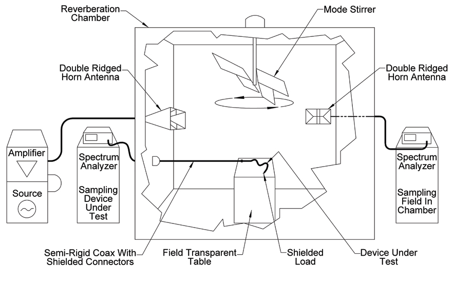 The test setup is depicted in Figure #1. Briefly, the test process is accomplished within a reverberation chamber. An amplified signal at a fixed frequency is injected into the chamber via a double-ridged horn antenna. Meanwhile, an electrically large tuner, located within the chamber turns at a constant and repeatable rate. The purpose of the tuner is to change the boundary conditions within the chamber so that, ideally, an even field strength is obtained everywhere within the chamber. As the tuner rotates, a second horn antenna samples the injected field. A spectrum analyzer, located outside the chamber records the maximum field strength measured within the chamber.
Concurrently, a cable assembly (test sample) is located within the chamber and is supported on a dielectric slab. The test sample is terminated with a well shielded load and is connected to a second spectrum analyzer outside the chamber via a semi-rigid assembly. The second spectrum analyzer records the maximum field strength able to leak into the test sample. The difference between the chamber maximum field strength and the test sample maximum field strength is the shielding effectiveness of the test sample, once differences in path losses have been taken into account.
Results
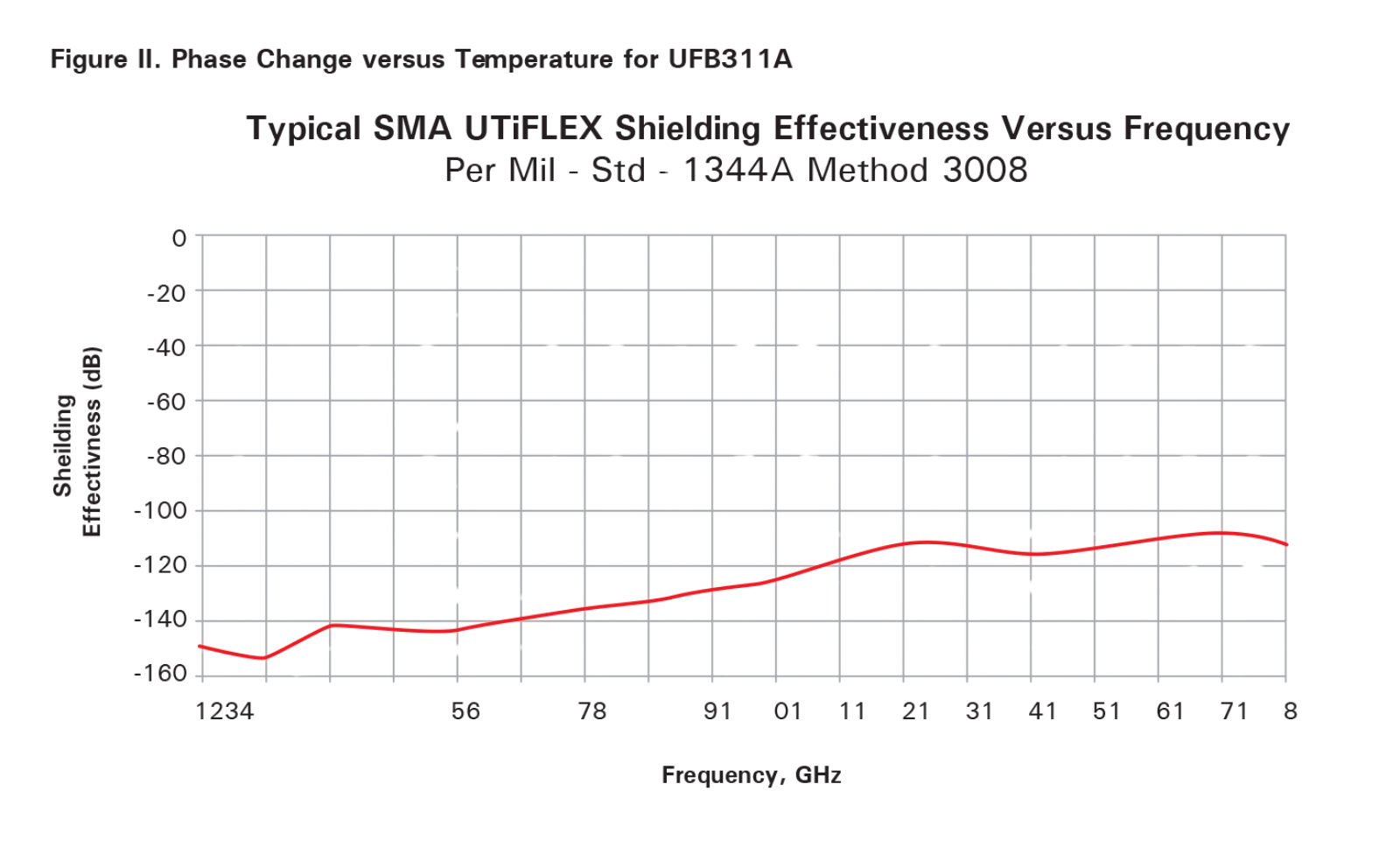
UTiFLEX cable assembly shielding performance is dependent upon the frequency of interest, the chosen cable, and the specified connector. All UTiFLEX cable constructions are designed to exceed -90 dB shielding performance through 18 GHz. UTiFLEX internal termination processes are also designated to produce shielding performance in excess of -90 dB through 18 GHz. However, the interface or body of various industry standard connectors can exhibit shielding performance ranging from -90 dB to -120 dB at 18 GHz. Therefore, the shielding performance of a completed UTiFLEX assembly will depend upon the most poorly shielded component in the assembly. In the event that a poorly shielded connector is desired for an assembly that needs to be well shielded, Micro-Coax engineers are willing and able to design shielding solutions for your cable assembly needs. An example of typical UTiFLEX assembly shielding performance from 1-18 GHz is depicted in Figure 2. The reliability of shielding performance values using either of the stated methods is typically +/- 5 dB.

References
MIL-STD-1344A Method 3008“Design, Evaluation, and Use of a Reverberation Chamber for Performing Electromagnetic Susceptibility/Vulnerability Measurement”, NBS Technical Note 1092, Issued April, 1986, M. L. Crawford and G. H. Koepke. “Mode-Stirred Chamber for Measuring Shielding Effectiveness of Cables and Connectors, An Assessment of MIL-STD-1344A, Method 3008”, IEEE 1988 International Symposium on Electromagnetic Compatibility, M. L. Crawford and J. M. Ladbury. IEC 61000-4-21 “Testing and measurement techniques- Reverberation chamber test methods”, Annex F “Shielding effectiveness measurements of cable assemblies, cables, connectors, waveguides and passive microwave components.”
Subscribe Now!
Interested in receiving email newsletters and other updates from Micro-Coax? Subscribe to receive our quarterly newsletter, product updates and more.